SOLO · HARD SURFACE · SIMULATION ASSET

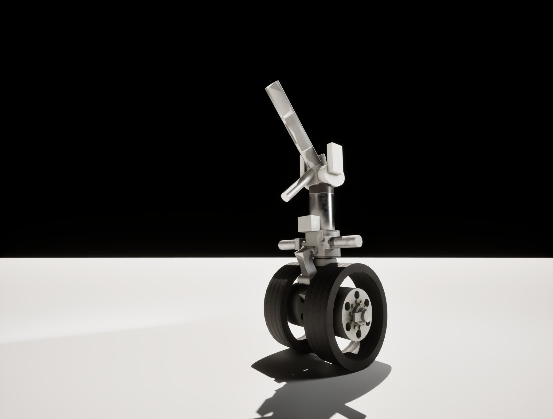
A320 Nose Landing Gear

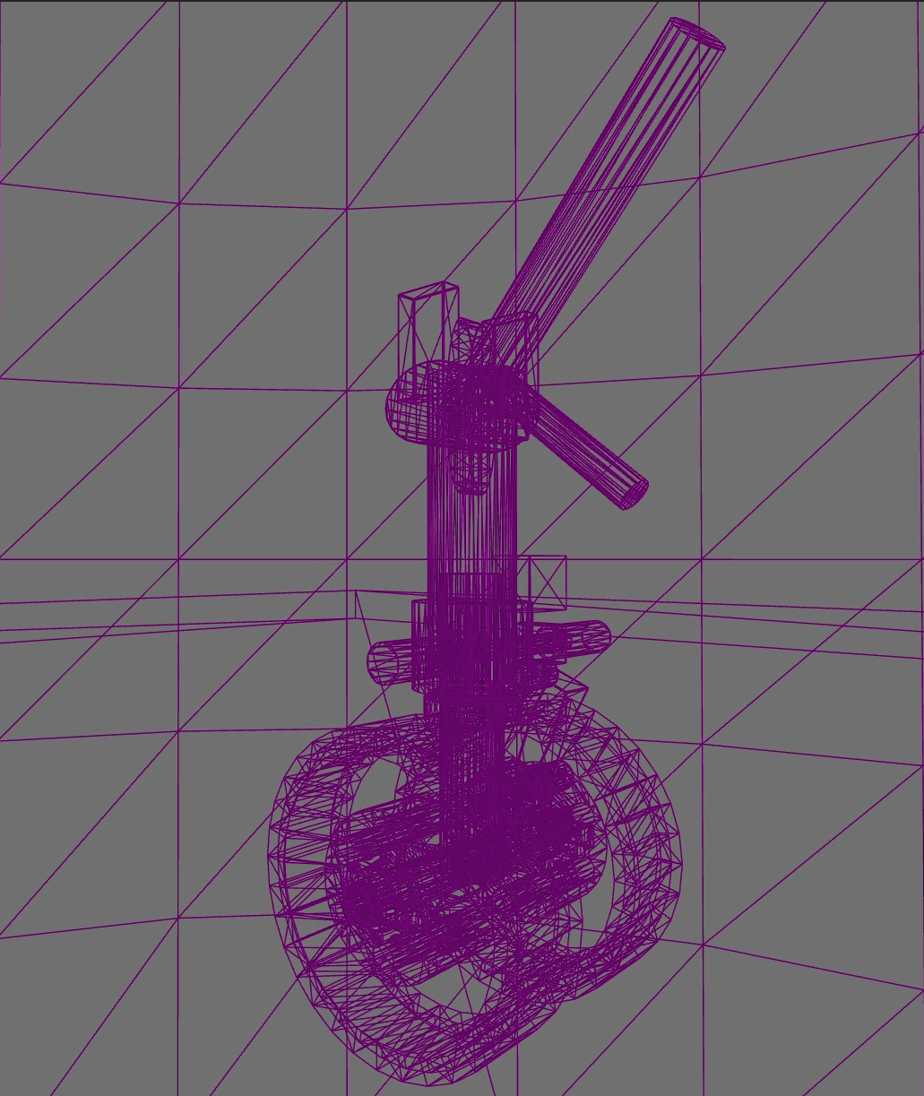
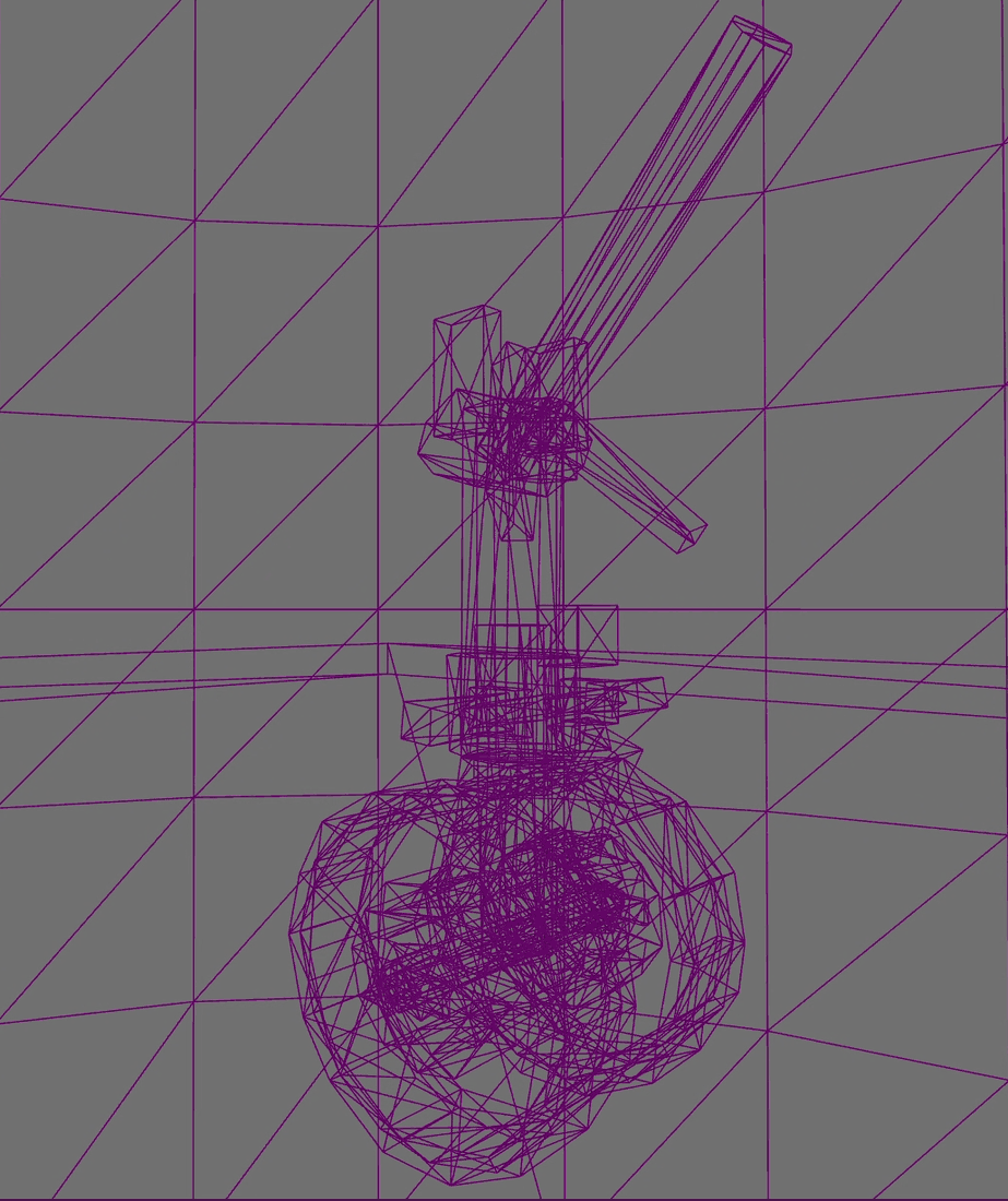
A real-time nose gear assembly built to the standard a simulation or training pipeline actually asks for: modelled to published aircraft dimensions, textured across four PBR sets, cut to LODs with recorded tri counts, and delivered into Unreal Engine 5.

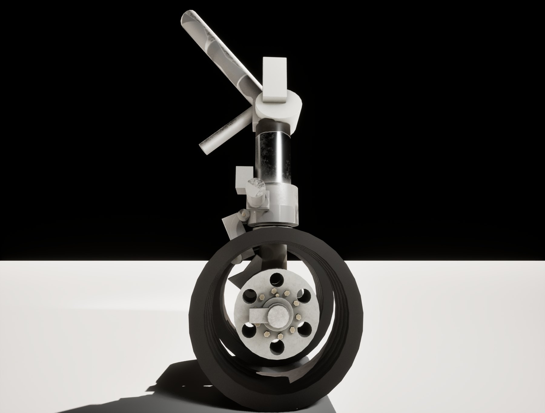
A320 nose landing gear, three-quarter render

Overview

Simulation and visualisation studios do not hire on mood. They hire on whether an asset arrives clean, correctly scaled, correctly named, and cheap enough to run in a real-time scene alongside several hundred others. This piece was built to be judged on those terms. It is the nose landing gear of an Airbus A320, modelled from walkaround reference and published dimensions rather than from a generic gear leg, with the whole pipeline from blockout to engine import documented as it went.

SUBJECT
Airbus A320 nose landing gear
SOFTWARE
Blender · Substance 3D Painter · Unreal Engine 5
TRIANGLES (LOD0)
9,500
TEXTURE SETS
4 · 2048 px PBR metal-rough
LODS
LOD0 to LOD3
OBJECTS
41 separate meshes
TIMELINE
8 to 19 September 2026
STATUS
Complete · Imported to UE5
ROLE
Solo · modelling, UVs, texturing, LODs, integration

Reference and research

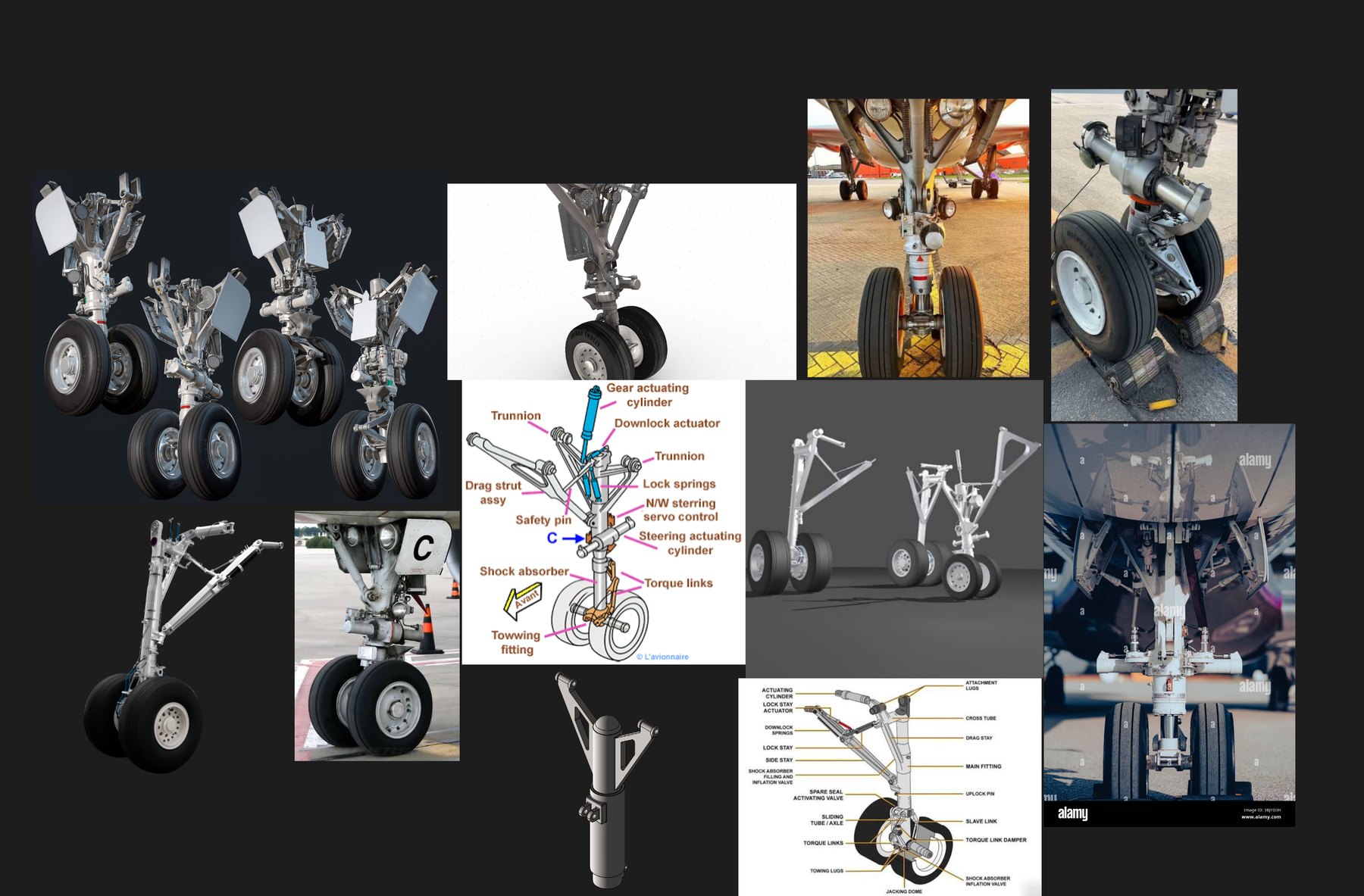
The gear was built against a reference board of walkaround photography rather than a single hero image, so that parts hidden in any one view still had a source. Dimensions were taken from published figures, not estimated from photographs.

No brake assembly, and that is correct

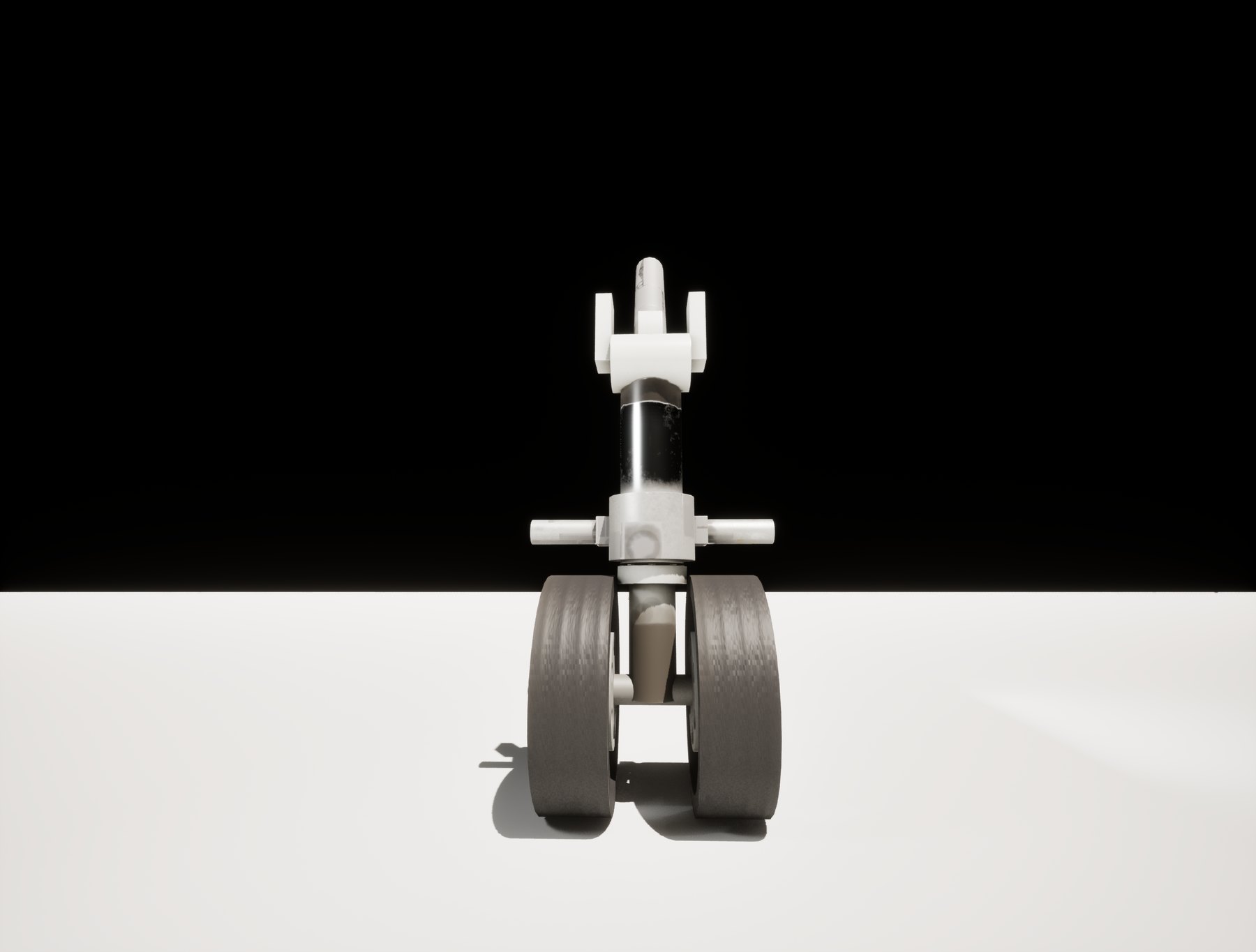
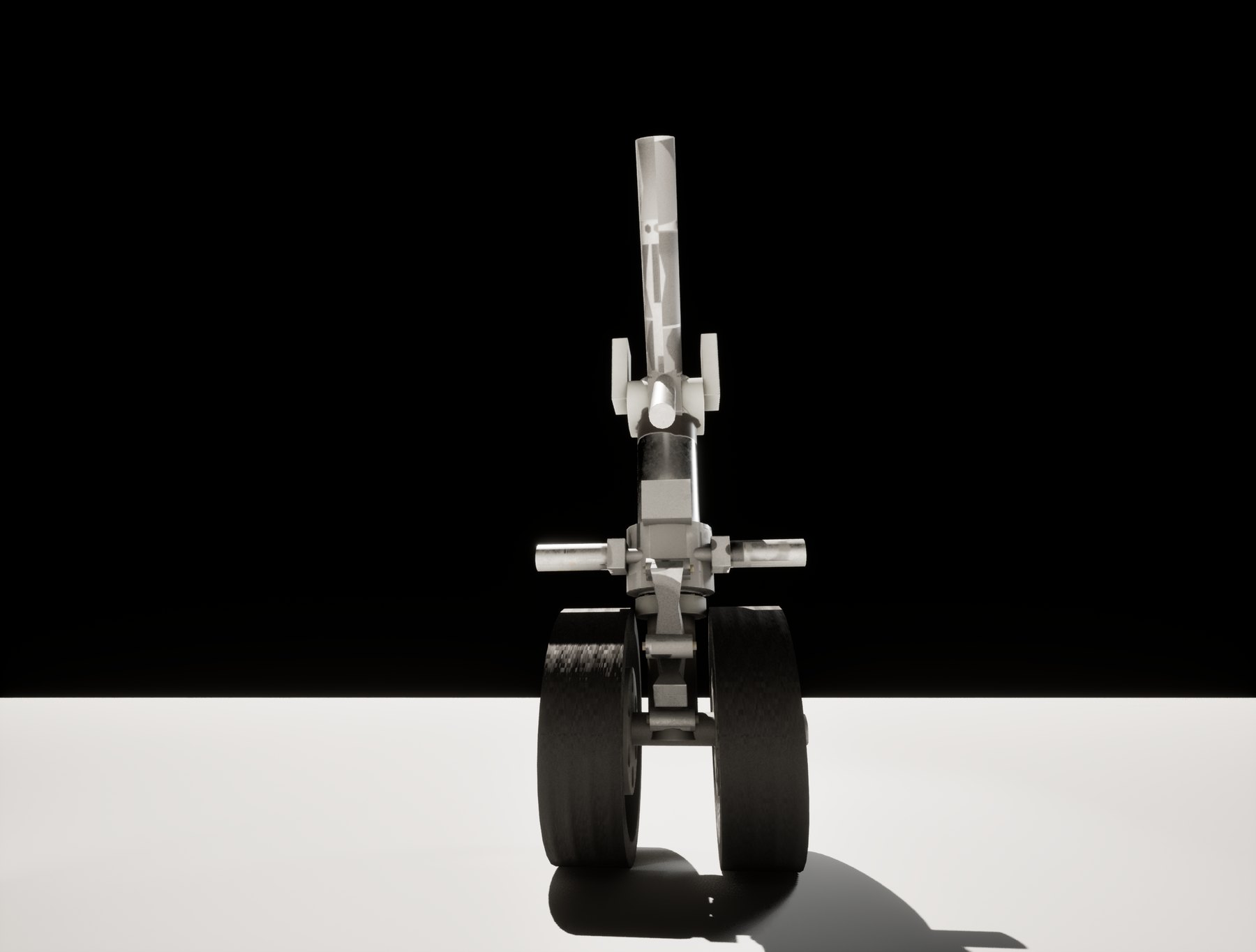
The A320 nose gear is free-rolling. Braking is carried entirely by the main gear, so there is no brake unit, no torque plate and no hydraulic brake line on this assembly. Modelling one would have been a visible error to anyone who works on aircraft.

This is the kind of detail that separates an asset built from the actual aircraft from one built from a generic gear leg, and it is the reason the reference stage took as long as it did.

TIRE SPECIFICATION
30 x 8.8 R15
TIRE DIAMETER (MODELLED)
76 cm (22.4 cm section width)
ASSEMBLY HEIGHT
225 cm
STRUT DIAMETER
22 cm outer, 80 cm long
SCENE UNITS
Metric · scale applied at source
REFERENCE SOURCES
Walkaround photo board, public aviation photography

Texturing

Four texture sets, grouped by how the material behaves rather than by which object it sits on. That grouping is what lets a chrome oleo, a bare actuator rod and a cad-plated fastener share one set without fighting each other.

MAT_STRUT
Polished chrome oleo, bare actuator rods, cad-plated hardware. Separated within the set by ID map rather than by splitting the mesh.
MAT_MECH
The structural body of the gear — main fitting, stays, torque links, brackets. The largest set and the one carrying most of the wear.
MAT_WHEELS
Wheel hubs and rims, with brake-dust-free surface treatment appropriate to a free-rolling nose wheel.
MAT_TIRES
Rubber with circumferential tread. Unwrapped as a straight rectangle, which is what made procedural tread authoring possible.

Tread is a height map, not geometry

The four circumferential grooves are authored in Substance as a height-channel fill layer driven by a stripe procedural, masked to the tread band. No tread geometry exists in the mesh at all, which keeps the tire cheap while reading correctly at any distance a trainee would see it from. This only worked because the tire was unwrapped as a clean straight rectangle: a warped or islanded tire UV would have made the stripe procedural unusable and forced the tread into geometry.

Texel density

Density is consistent within each texture set, enforced by unwrapping each set in multi-object edit mode and running Average Islands Scale. Consistency between the four sets was verified visually with a colour grid checker rather than measured numerically, so no pixels-per-centimetre figure is claimed here. Where a studio needs that number to a spec, it is a measured pass rather than a rebuild.
Problems worth naming

Four things that were not obvious going in, and how they were solved.

  1. 01 Isolating parts inside a shared texture set. A polished chrome oleo, a bare steel actuator rod and a cad-plated fastener needed completely different treatments while sharing one set. Rather than splitting the mesh, an ID map was baked using Mesh ID / Polygroup as the colour source, and colour-selection masks were used in Substance to isolate each part. One set, three materials, no extra draw calls.
  2. 02 Baking mesh maps without a high-poly. The low-poly was used as its own high-poly for the normal, AO, curvature, thickness and position bakes. That works here because the bevels are real geometry rather than a normal-map trick, so the bake had genuine edge information to read. It saved roughly a day of high-poly work with no meaningful quality loss at the resolution this asset is viewed at.
  3. 03 Texture sets by material behaviour, not by object. Sets were driven by material assignment in Blender and grouped by how a surface behaves under light, which is why the strut set spans several unrelated parts and the mech set spans most of the structure. Grouping by object would have produced more sets, more draw calls, and inconsistent wear across parts that sit right next to each other.
  4. 04 Mirroring parts built with arrays. Radial bolt patterns were built with an Empty-offset array, which stores a relationship to the Empty rather than an absolute rotation. Mirroring those objects made the copies spiral instead of mirroring cleanly. The fix was to apply the array first, turning it into real geometry, and mirror that. Worth knowing before it eats an evening.

LODs

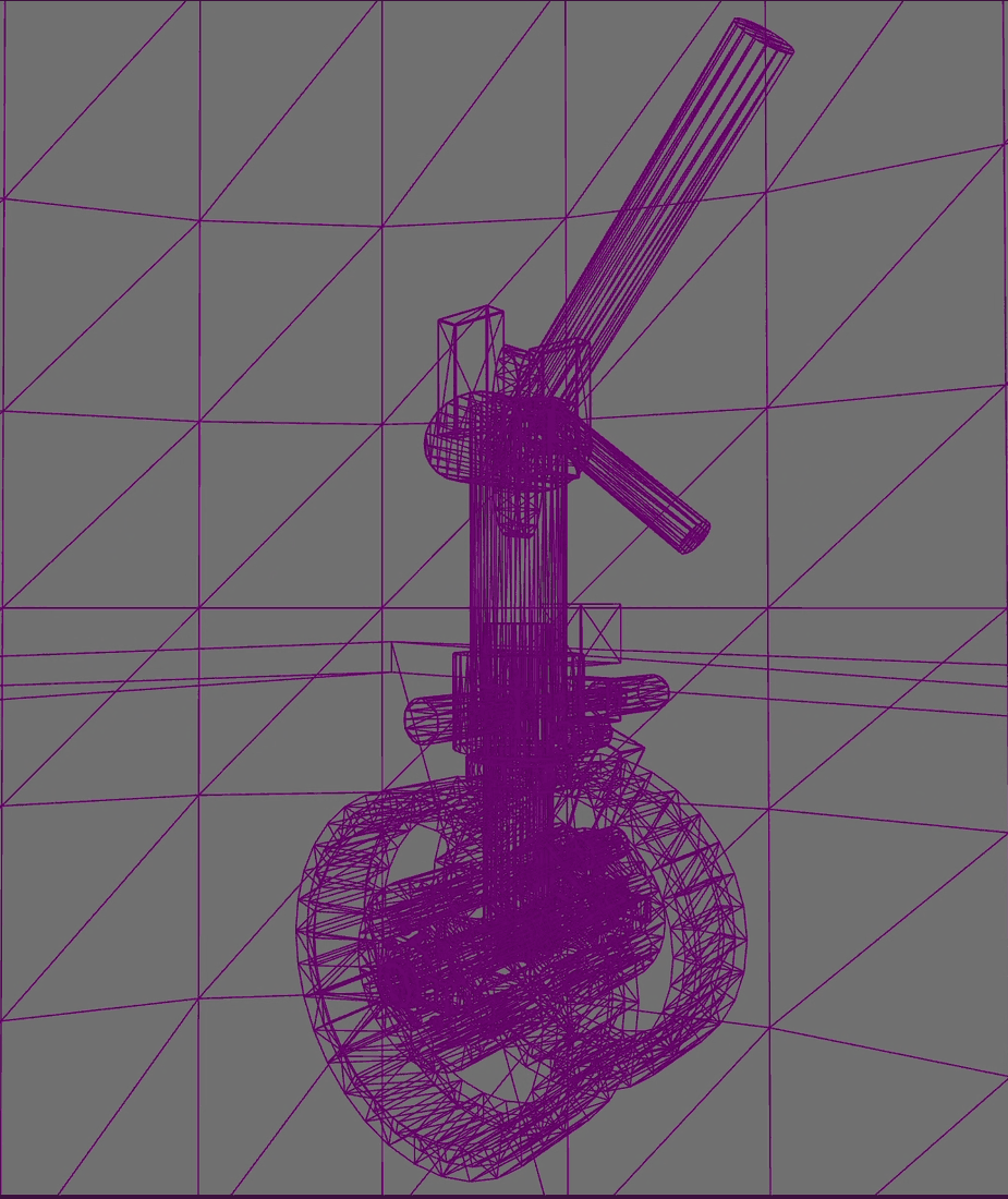
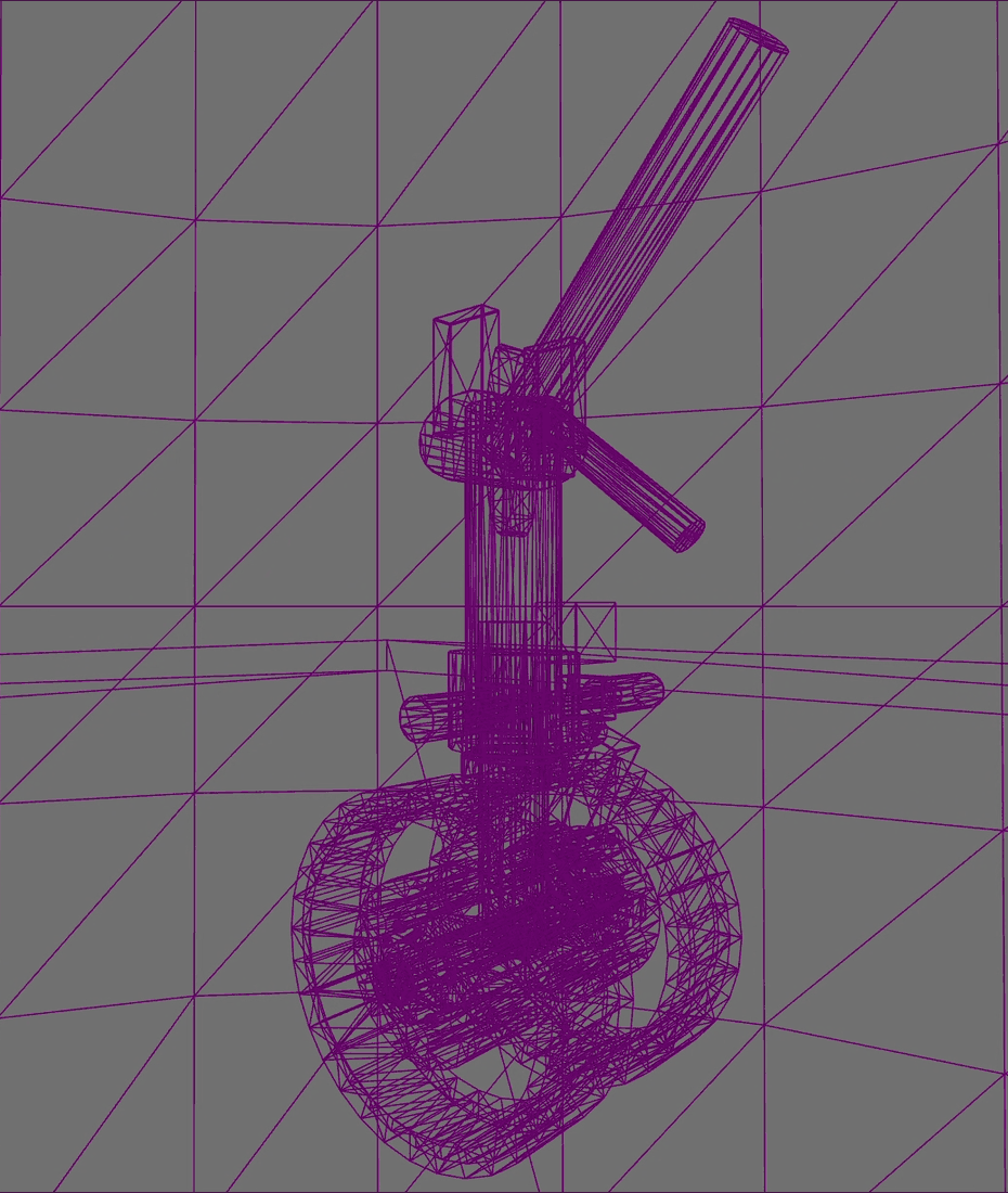
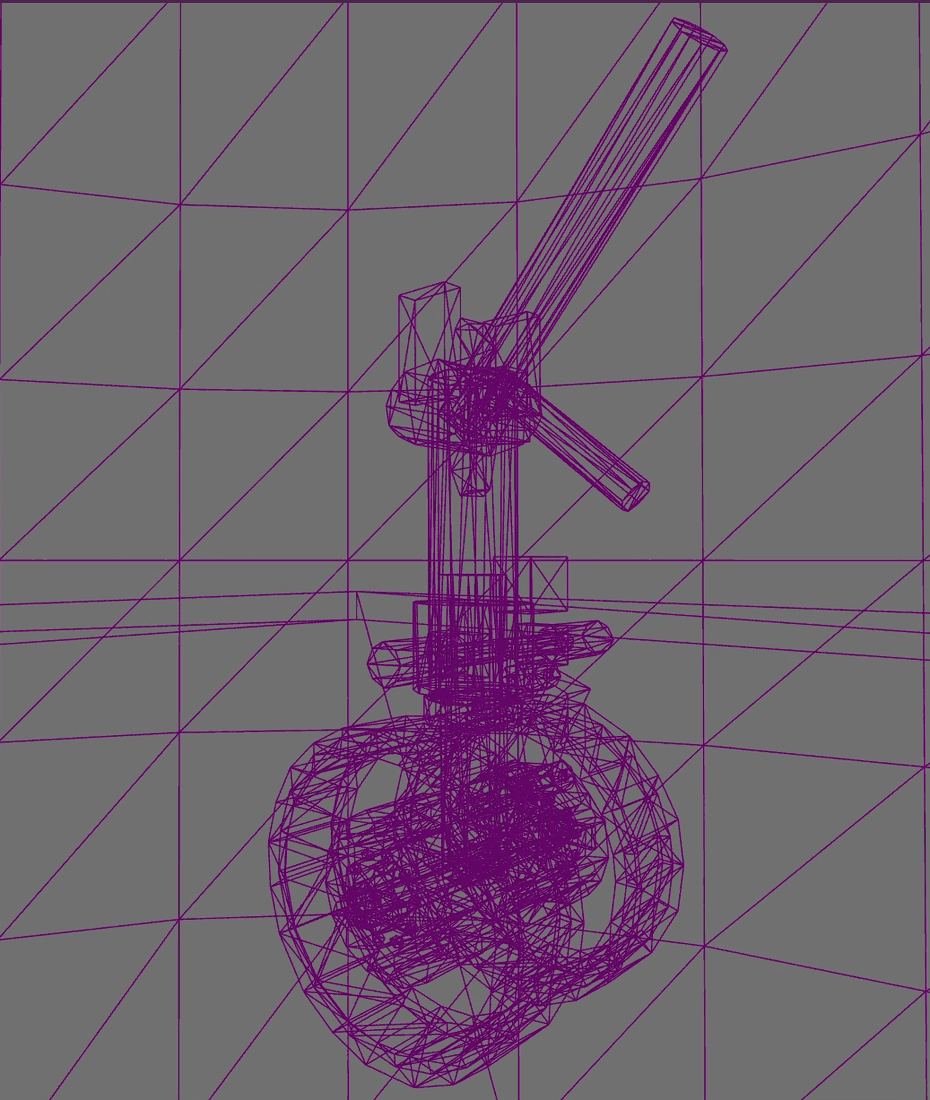
Four levels generated with Unreal's built-in mesh reduction on a halving chain, each checked in the editor for silhouette preservation. Counts read from the engine rather than estimated.

LOD0
9,500 tris
LOD1
4,750 tris
LOD2
2,374 tris
LOD3
1,188 tris

In engine

Imported to Unreal Engine 5 with LODs assigned, materials rebuilt from the exported PBR maps, and the assembly checked at the distances a trainee or operator would actually view it from.

Documentation

The build was documented as it happened rather than reconstructed afterwards: a build plan with the scope and dimensional targets set up front, a running build log, and a handover pack covering naming conventions, texture set assignments, LOD counts and export settings. That documentation is part of the deliverable, because in a simulation pipeline an undocumented asset is an asset someone else has to reverse engineer.

Download the documentation pack (PDF)